Introduction
In one of my lab courses, I had the opportunity to design and build a PCB. This process involved performing calculations for the circuit components, creating a schematic, and then translating that schematic into a PCB layout using Eagle CAD software. After designing the board, it was printed, and I had the chance to attach actual components like resistors, capacitors, and op-amps using a soldering machine. This entire experience was incredibly enriching, providing me with valuable hands-on experience in PCB design and assembly, a skill I found both challenging and rewarding.
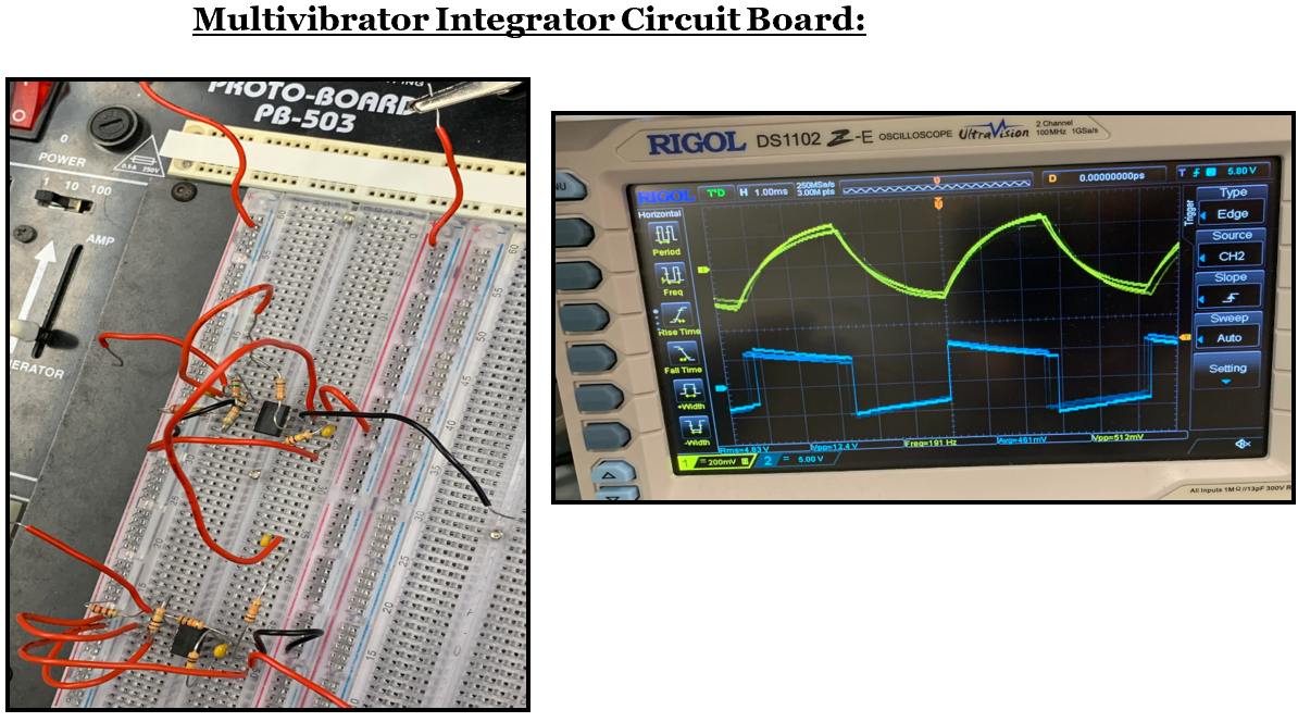
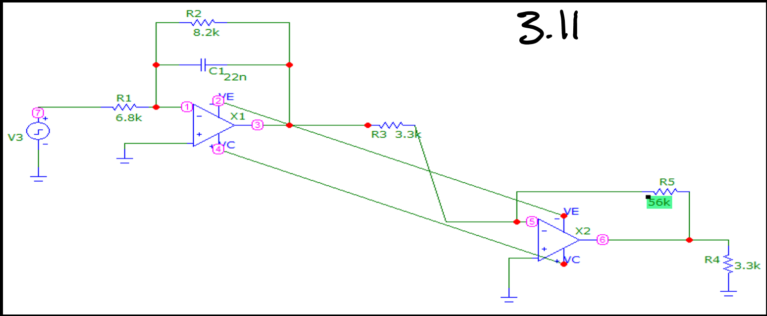
Multivibrator Integrator (Square & Triangle):
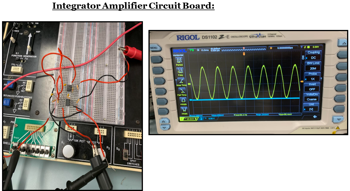
Integrator Amplifier (Sine Waveform):
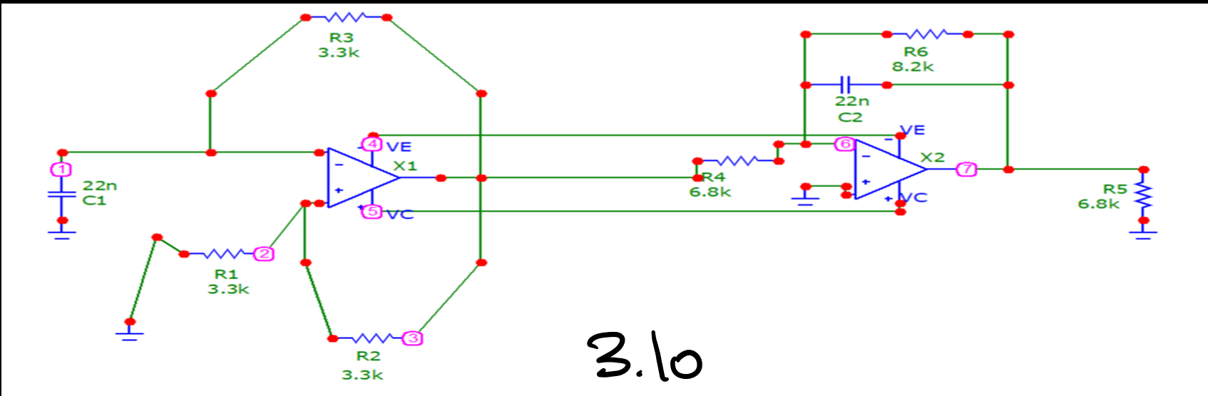
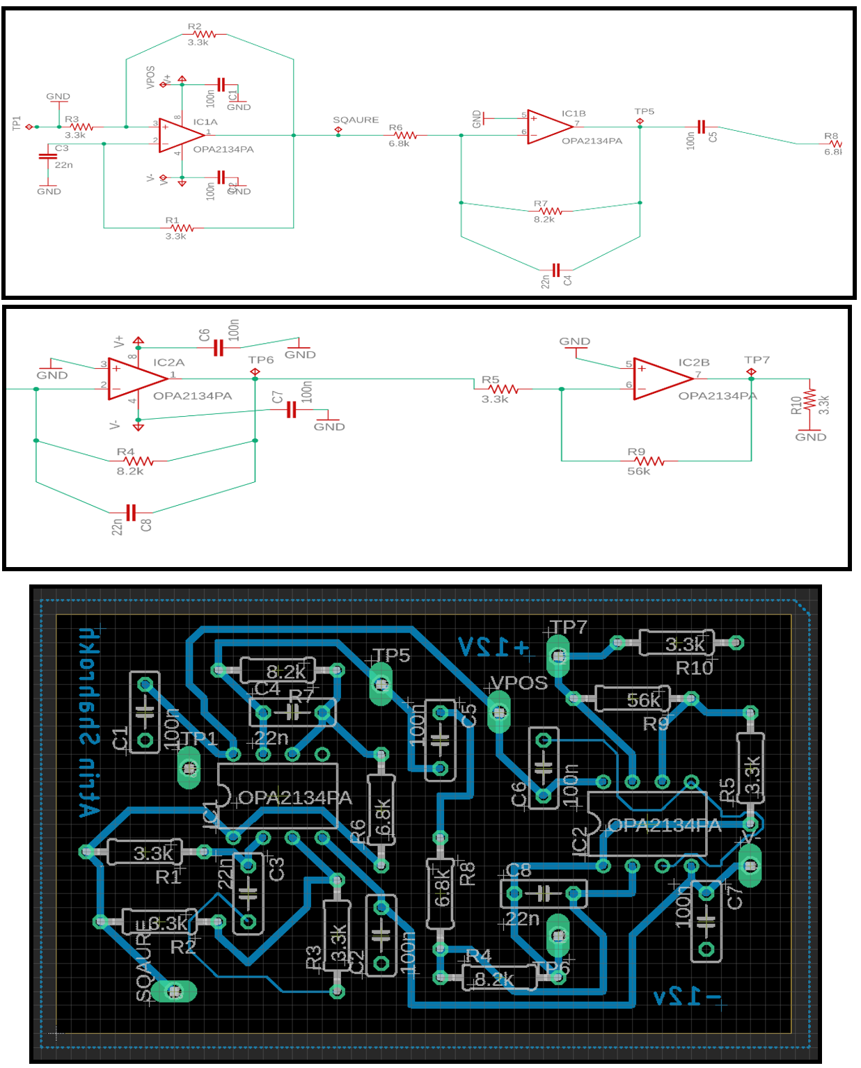
Eagle Schematic & Board:
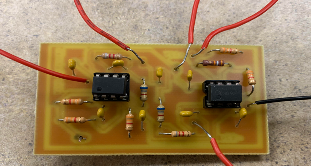
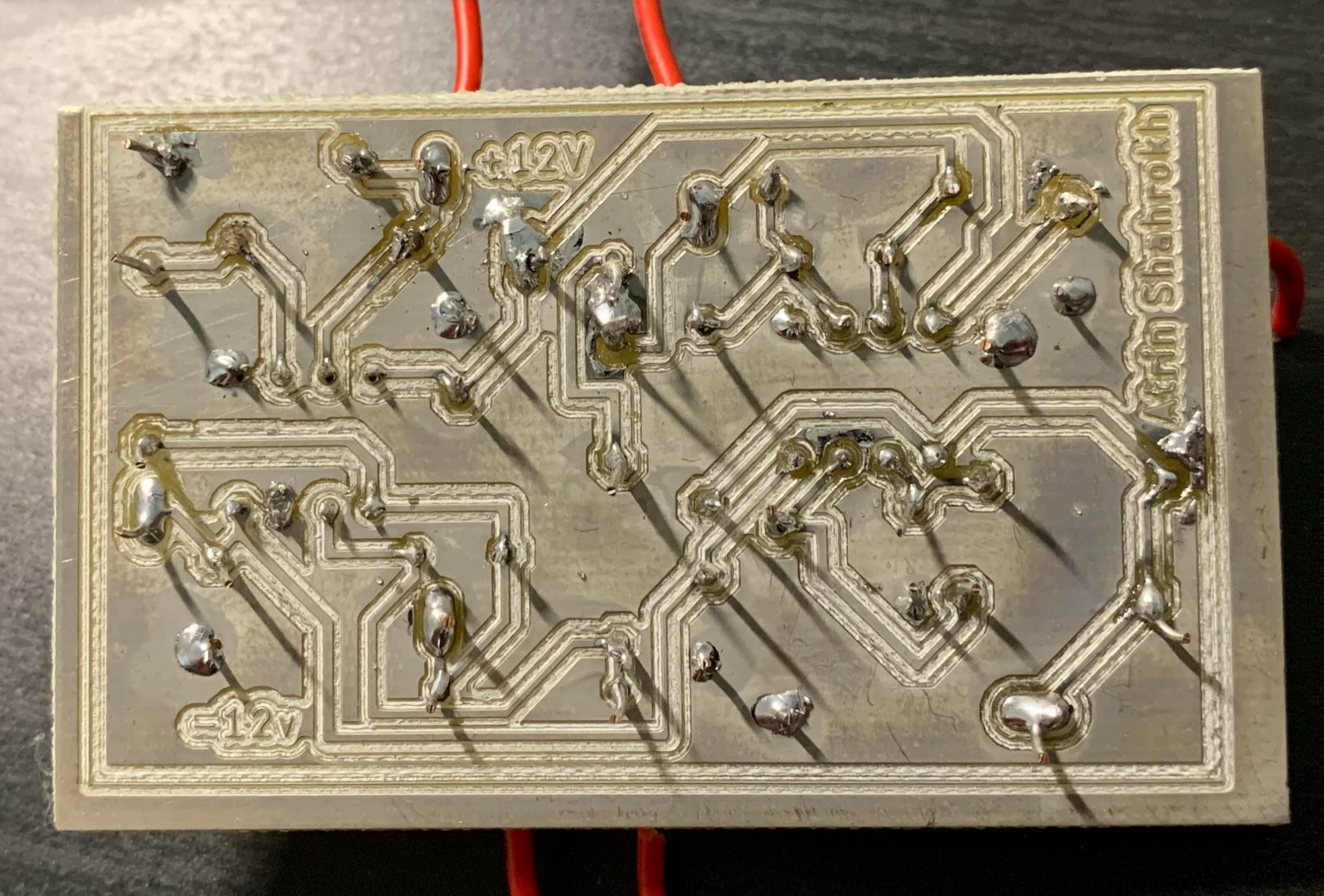
Soldered Circuit Board: